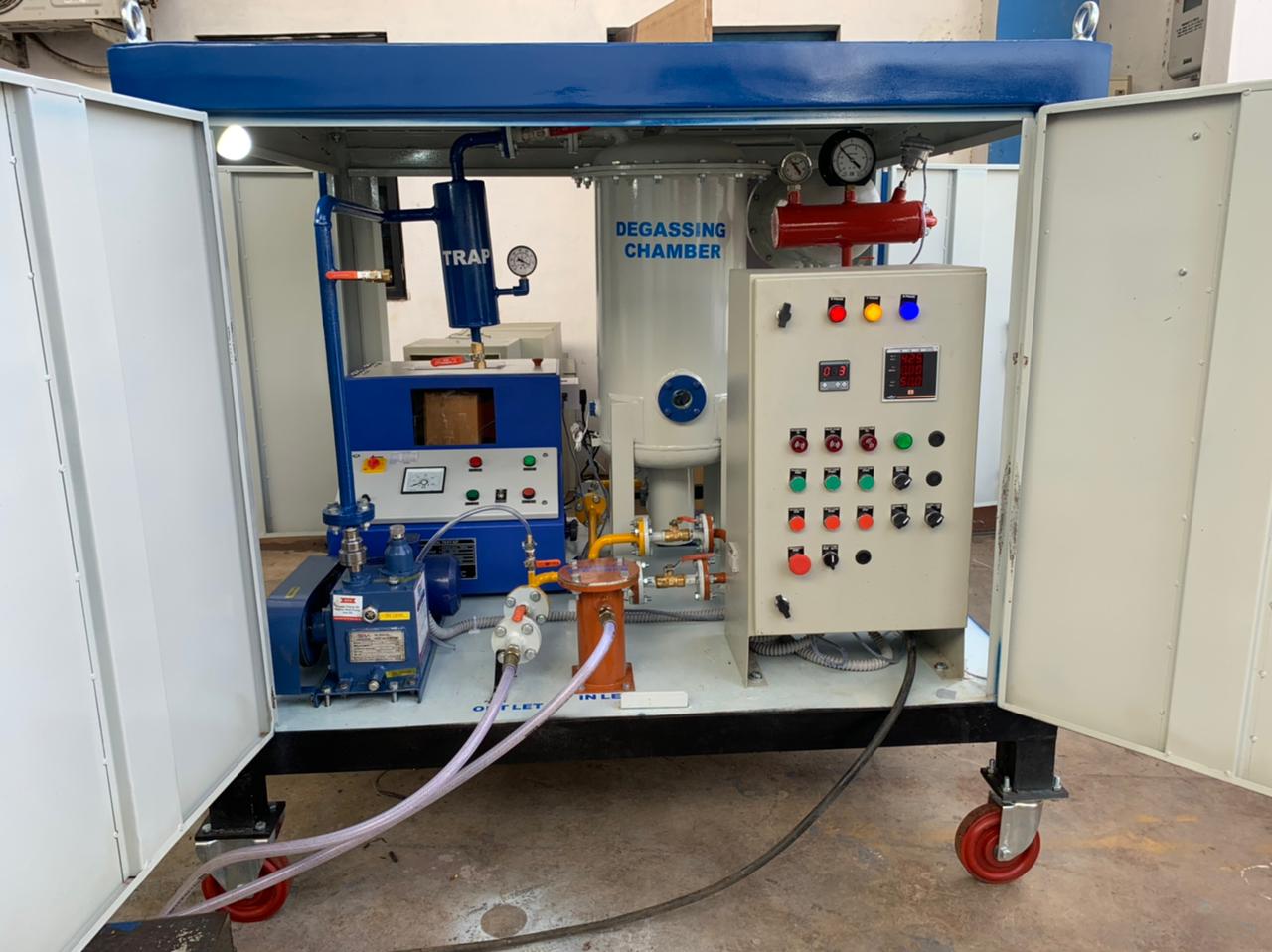
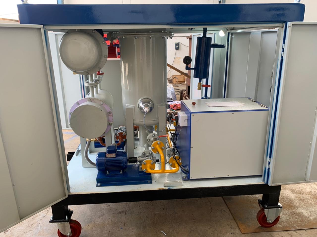
PORTABLE TYPE 600LPH SINGLE STAGE HIGH VACUUM TRANSFORMER OIL FILTRATION PLANT
The plant shall be suitable for treating transformer & switchgear oil by first heating it and then passing it through specially designed filter and then subjecting it to high vacuum treatment which dehydrates and degasifies the oil to the following specifications after completion of the process.
The plant shall not require any special tools for operation and maintenance.
|
PARAMETERS |
BEFORE PROCESSED OIL |
AFTER PROCESSED OIL |
|
Break down voltage( across 2.5 mm gap ) |
20 KV |
60 > 70KV |
|
Moisture content |
50 PPM |
5 PPM |
|
Suspended particles |
Visible to naked eye |
1 Micron |
|
Gas content |
10% by volume |
0.1% by volume |
The oil filtration plant shall be designed for high vacuum and low temperature of oil for achieving required results. The oil filtration plant shall be PORTABLE TYPE SKID TYPE 04 PU CASTER WHEEL MOUNTED MOBILE PLANT MACHINE, the plant shall be weather proofed and shall be suitable for outdoor use. The casing shall be provided with doors of CRCA sheets, hinged on fabricated framework, angles and channels to have access to the operational controls and inspection windows etc. the equipment shall be enclosed and protected against climatic conditions. All components shall have adequate strength and rigidity to withstand normal conditions of handling transport and usage and shall be free from edges or corners to avoid injury to operating personnel in normal conditions of use. The design of the plant shall be such that if required the part/s can easily be replaced. Proper guarding arrangement shall be provided on all such parts which due to their position and nature of operation are liable to cause accidents.
The plant shall consist of the following
01. INLET PUMP
A positive displacement gear type pump with a capacity Of 600 LPH shall be provided. The pump shall be thoroughly tested for vacuum and shall be suitable continuous trouble free operation. The pump shall be provided with automatic protection against over-pressure build-up. Interlocking arrangement shall be provided in between the oil inlet pump and the heater so that heater cannot be energized unless inlet pump is on. Interlocking arrangement shall be provided in the filter plant between the inlet pump and high level float switch (located into degassing column) to avoid excessive rise of oil in the degassing column. Flow control valve for adjustment of flow rate through filter, a flow control valve shall be provided across the gear pump. The suction head of the inlet feed pump at atmospheric condition at inlet shall be 4 to 5 mtrs.
02. HEATERS
Heaters shall be provided in protection tubes to avoid localized overheating, hotspot and breaking oil. Heaters shall be capable of heating oil from 30oC to 60oC. Temperature during degassing and dehydration for good results should not exceed 60oC. Heaters shall be thermostatically controlled. Total heater power shall be 30 KW. Heaters shall be divided into One groups.
EACH HEATER LOAD = 1.5 KW,
TOTAL HEATER NOS= 5,
TOTAL HEATER LOAD=7.5 KW
Heater elements shall be of Nichrome/ Kanthal wire filament, inserted in refractory formers which are located in protection tubes. Construction of the heat exchanger shall be such that the replacement of heaters shall be easy and shall not require any special tools.
Heaters shall be interlocked with gear pump and shall not be in ON position, unless the Inlet Pump is working. Heater Tank shall be adequately thermally insulated to minimize loss of heat.
Heater Pipe surface density shall not be more than 2.0 Watt/cm2.
Each group of Heaters shall be controlled by thermostat. A safety thermostat shall be provided to take care of any accidental rise of temperature of oil and shall put off the Heaters in such eventuality. This thermostat shall be set at slightly higher temperature than that of controlling Thermostats. There will be preset safety thermostat before digital temperature controller.
One suitable Pressure Relief Valve shall be provided on the Heater Chamber to prevent any pressure rise above the acceptable limit.
03. FILTRATION SYSTEM
Filtration System shall consist of the following:
(A) PRELIMINARY FILTER- ( MAGNETICK STAINER)
The main function of this Filter shall be to prevent any damage to the Inlet Pump. It shall have strainers capable of retaining all particles above 1 mm size and also magnetic particles. Incoming oil shall pass through this Filter. (Filter housing designed for easy cleaning / replacement of the choked cartridges) without dismantling the pipeline.
( B) CARTRIDGE FILTER
Non-hygroscopic throw away type Cartridge Filters of one 01 Micron rating shall be provided. This Cartridge Elements shall have large dust holding capacity. The replacement of Cartridge Elements is very easy and can be done without any special tools. The Housing / Vessel are suitable for high vacuum and pressure applications. Compound (Pressure / Vacuum) Gauge shall be provided on Filter Vessel for inlet pressure indication in order to ascertain condition of Cartridge Elements. Aeration shall be provided on the Filter Vessel to aerate the Vessel during draining. The Cartridge type Filter shall facilitate to achieve desired value of particle size in micron.
04. DEGASSING AND DEHYDRATION CHAMBER – SINGLE STAGE
The Degassing Chamber shall function as degasser and dehumidifier & shall be capable of removing dissolved gases and moisture from the oil. It shall be of M.S. and shall have welded construction. The Chamber shall be able to withstand the vacuum to which it shall be subjected. Efficiently spread Reaching Rings shall be placed in the Degassing Columns. The surface area offered by the reaching Rings shall be sufficient to form a thin film of oil and shall facilitate removal of dissolved gases and moisture at the rated flow rate of oil. A Slight Glass with Illuminating Lamp shall be provided for observation of oil flow one no’s of Float Switch on the Degassing Chamber shall be provided for preventing excess rise of oil / foam level. It shall be electrically interlocked with Inlet Pump. Single stages shall be separated by a Siphon Seal.
05. VACUUM PUMPING SYSTEM (FOR DEGASSING COLUMN)
A high efficiency rotary Vacuum Pump shall be provided for evacuation of Degassing Chamber. The Pump shall be of reputed make. A Manufacturer’s specifications for the same are as given below for reference.
VACUUM PUMP– ROTARY VAN VACUUM PUMP (1 No.)
Nominal Pumping Speed 0.6 M3/Hr (100 LPM)
Ultimate Vacuum with G.B. Closed 5 x 10⁻² Torr
Ultimate Vacuum with G.B. Open 5 x 10⁻¹ Torr
Make: S V ENGINEERING
06. DISCHARGE PUMP
A Rotary Gear type Discharge Pump with a capacity of 600 LPH, suitable for sucking oil from the Degassing Chamber held under vacuum, shall be provided. This shall be fully tested for pressure and vacuum leak rate.
The Discharge Head of the Outlet Pump shall be 15 Mtrs.
07. MECHANICAL NON RETURNE VAVE
One number of mechanical none -return valve will be provided at inlet and another at outlet of the filter plant to prevent mixing of processed and un processed oil, which may happen in case of power failure.
08. PRESSIURE RELIEF VALVE
It is connected in shunt with oil inlet pump. It opens if the pressure exceeds predetermined value and returns oil to its source and prevents damage to the plant
09. FLOW CONTROL VALVE
For adjustment of flow rate of flow control valve will be provided across the gear pump.
10. OIL SAMPLING VALVE
This valve shall be provided to collect the sample of oil for testing during operation.
11. AIRING VALVE
Degassing Chamber is provided with an airing valve to admit air into oil Filtration Plant and bring it to atmospheric pressure. One airing valve is provided in vacuum line of Rotary Oil Sealed pump. It is essential to admit the air and bring the oil to atmospheric pressure and then switch off the pump. This prevents the suck back of the pump oil.
12. FLOAT SWIT
Two nos. float switch on the degassing chamber shall be provided for preventing excess rise of level. It shall be electrically interlocked with the inlet pump. Another float switch shall be provided to control the low level of oil in the degassing chamber. It shall be electrically interlock with the discharge pump.
13. GAUGES & INSRUMENT
Ø Temperature Gauge
Ø Compound gauge
Ø Vacuum Gauge –Bourdon Type
Ø Sigh Glass In Degassing Chamber
Ø Temperature Indicator Cum Controller
Ø Volt Meter & Amp Meter
14. INDEPENDENT MOTOR
Independent Motor for Oil Discharge Pump, Oil Inlet Pump & Vacuum Pumps shall be provided. Motors shall confirm generally to IS: 325 (Testing) shall be of Class ‘F’ Insulation. Starters shall be of direct On-line type. Motors shall be of MEGHA ROTO TECH PVT LTD make.
15. CONTROL PANEL
Base mounted Control Panel comprising of all wiring will be arranged into flat or rectangular groups and shall be supported with cleats. All wiring will be of single conductor copper wire insulated with insulations suitable for hot and moist tropical conditions. The wire ends will be provided with suitable lugs for connecting it to terminals.
All necessary Manual Switches, Lamps, Contactors, Overload Protection for Motors and Relays for Isolation. Audio Annunciation
- High Oil temperature.
- Inlet pump motor trip
- Outlet pump motor trip
- Vacuum Pump motor trip
- High oil level in degassing chamber.
16. SIGHT GLASS WITH ILLUMINATING LAMP
Degassing Chamber is provided with illuminating sight glass to observe the processing of oil under vacuum.
17. DRAIN
The Plant will be provided with draining of the whole system just by operation of valves.
18. OIL HOSES – 2 NOS
Two numbers of Oil Hoses Each 10 Meters Size for inlet 15NB for Inlet and discharge with suitable connection on both side will be provided. Oil Hoses will be capable of handling the transformer oil with Vacuum.
19. PAINTING:
A) Oil heater, filter vessel, degasser shall be of mild steel construction the internal and external surfaces including oil heater, filter vessel, degasifier and structural steel work to be painted shall be shot shot or sand blasted to remove all rust and scale of foreign adhering matter or grease. All steel surfaces in contact with insulating oil shall be painted with two coats of heat resistant oil in soluble, insulating varnish.
B) All internal paints steel surfaces shall be given a primary coat of zinc chromate, second coat of oil and weather resistant varnish of a colour distinct from primary and final two coats of glossy and weather resistance paint.
C) All paint shall be carefully selected to with stand heat and extremes of weather. The paint shall not scale off or crinkle or be removed by abrasion due to normal handling.
D) Bolts & Nuts : All bolts and nuts exposed to weather shall be hot dip
Galvanized/cadmium plated and passivated /zinc plated and passivated.
E) Material of construction for vacuum pumps air compressor, air drying plant, air receiver shall be steel of suitable grade.
20. SURFACE TREATMENT
All exposed surfaces i.e. the external surface of oil pipeline, various tanks, complete chassis and whether proofing will be cleaned off rust, dirt, scale and foreign matter and will be applied with a coat of rust preventive compound before being painted.
For – Krisha Filter Equipments